4. FLAME GPU Simulation and Visualisation
4.1. Introduction
The processes of building and running a simulation is made easier described within this chapter as are a number of tools and procedures which simplify the simulation code generation and compilation of simulation executables. In order to use the FLAME GPU SDK it should be placed in a directory which does not contain any spaces (preferably directly within the C: drive or root or root operating system drive). The host machine must also be running windows with a copy of the .NET runtime (used within the XSLT template processor) and must contain NVIDIA GPU hardware with Compute level 1.0.
4.2. Generating a Functions File Template
Chapter Summary of Agent Function Arguments previously described the exact argument order for agent function declarations however in most cases it is sensible to use the provided XSLT template functions.xslt located in the FLAMEGPU/templates directory within the FLAME GPU SDK) to generate a agent function source file with empty agent function declarations automatically using your XMML model file.
Once this has been generated the agent function scripts can be implemented within the function declarations rather easily.
Care must however be taken in ensuring that if the XMML model file is later modified that the agent function arguments are updated manually where necessary.
Likewise be careful not to overwrite any existing function source file when generating a new one using the XSLT template.
Generation of blank function source files is not incorporated into the visual studio template project and must be manually accomplished.
A .NET based XSLT processor is provided within the FLAME GPU SDK for this purpose (XSLTProcessor.exe located in the tools directory) and can be used via the command line as follows (or via the GenerateFunctionsFileTemplate batch file located in the tools directory of the FLAME GPU SDK);
XSLTProcessor.exe XMLModelFile.xml functions.xslt functions.c
Alternatively any compliant XSLT processor such as Xalan, Unicorn or even Firefox web browser can be used.
4.3. FLAME GPU Template Files
The FLAME GPU SDK contains a number of XSLT templates which are used to generate the dynamic simulation code. A brief summary of the functionality and contents of each template file is as follows:
header.xsltThis template file generates a header file which contains any agent and message data structures which are common in many of the other dynamically generated simulation source files. The template also generates function prototypes for simulation functions and functions which are visible externally within custom C or C++ code.main.xsltThis template file generates a source file which defines the main execution entry point function which is responsible for handling command line options and initialising the GPU device.io.xsltThis template file generates a source file which contains functions for loading initial agent XML data files (see Initial XML Agent Data) into the simulation and saving the simulation state back into XML format.simulation.xsltThis template file generates a source file containing the host side simulation code which includes loading data to and from the GPU device and making a number of CUDA kernel calls which perform the simulation process.FLAMEGPU\_kernels.xsltThis template file generates a CUDA header file which contains the CUDA kernels and device functions which make up the simulation.visualisation.xsltThis template file generates a source file which will allow basic visualisation of the simulation using sphere based representation of agents in 3D space. The source file is responsible for CUDA OpenGL interoperability and rending using OpenGL. The source file includes a visualisation.h file containing a number of definitions and variables which is not generated by any templates and should be specified manually.
4.4. Compilation Using Visual Studio
The FLAME GPU SDK and examples are targeted at a specific CUDA and Visual Studio version. The Visual Studios XML editor includes validation support and XML tag auto completion which makes defining an XMML model incredibly easy. The following subsections describe the various aspects of a FLAME GPU project file and describe the build processes.
4.4.1. Visual Studio Project Build Configurations
The FLAME GPU examples and template project file contain build configurations 64 bit Windows (x64) environments. 32 bit windows has been removed due to limitations on GPU memory addressing since version 1.3.0.
For each platform the project also contains four configurations for debugging (Debug) and release versions (Release) of both console based simulation and visualisation simulation.
The two debug options disable all compiler optimisations and generate debug information for debugging host (non GPU) code and enables CUDA device emulation for GPU (device) debugging.
The visualisation configurations enable building of visualisation code and specify a pre processor macro (VISUALISATION) which is used by a number of pre-processor conditionals to change the simulations expected arguments (see Simulation Execution Modes and Options).
4.4.2. Visual Studio Project Virtual File Structure
Within the FLAME GPU examples and template projects code is organised into the following virtual folders;
FLAME GPUConsisting of a folder containing the FLAME GPU XML schemas and Code generating templates. These files are shared amongst all examples so editing them will change simulation code generated for other projects.FLAMEModelContains the XMML model file and the agent functions file (usually calledfunctions.c). Note that thefunctions.cfile is actually excluded from the build processes as it is built by the dynamically generatedsimulation.cusource file which includes it.Dynamic CodeContains the dynamically generated FLAME GPU simulation code. This code will be overwritten each time the project is built so any changes to this files will be lost unless template transformation is turned off using the FLAME GPU build rule (see FLAME GPU Build Rule Options).- Additional Source Code This folder should contain any hard coded simulation specific source or header files. By default the FLAME GPU project template defines a single
visualisation.hfile in this folder which may be modified to set a number of variables such as viewing distance and clipping. Within the FLAME GPU examples this folder is typically used to sore any model specific visualisation code which replaces the dynamically generated visualisation source file.
The physical folders of the SDK structure a self explanatory however it is worth noting that executable files generated by the Visual Studio build processes are output in the SDKs bin folder which also contains the CUDA run time dlls.
4.4.3. Build Process
The Visual Studio build process consists of a number of stages which call various tools, compilers and linkers.
The first of these is the FLAME GPU build tool (described in more detail in the following section) which generates the dynamic simulation code from the FLAME GPU templates and mode file.
Following this the simulation code (within the Dynamic Code folder) is built using the CUDA build rule which compiles the source files using the NVIDIA CUDA compiler
nvcc.
Finally any C or C++ source files are compiled using MSVC compiler and are then linked with the CUDA object files to produce the executable.
To start the build processes select the Build menu followed by Build Solution or use the F7 hotkey.
If the first build step in the Visual Studio skips the FLAME GPU build tool a complete rebuilt can be forced by selecting the Build menu followed by Rebuild Solution (or Ctrl + Alt + F7).
4.4.4. FLAME GPU Build Rule Options
The FLAME GPU build rule is configured by selecting the XMML model file properties. Within the Build rule the XSLT options tab (see Figure) allows individual template file transformations to be toggled on or off. These options are configuration specific and therefore console configurations by default do not processes the visualisation template.

FLAME GPU Build Rule XSLT Options Tab
4.4.5. Visual Studio Launch Configuration Command Arguments
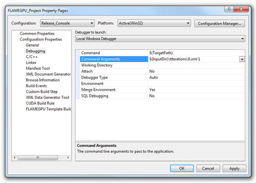
In order to set the execution arguments (described in the next section) for simulation executable in any one of one of the four launch configurations, the Command Arguments property can be set form the Project Properties Page (Select Project Menu followed by FLAMEGPU\_Project Properties).
The Command Arguments property is located under Configuration Properties -> Debug (see Agent Function Scripts and the Simulation API).
Each configuration has its own set of Command Arguments so when moving between configurations these will need to be set.
Likewise the Configuration Properties are computer and user specific so these cannot be preset and must be specified the first time each example is compiled and run.
The Visual Studio macro $InputDir can be used to specify the working directory of the project file which makes locating initial agent data XML files for many of the examples much easier (these are normally located in the iterations folders of each example).
The Command Arguments have been set the simulation executable can be launched by selecting Start Debugging from the Debug menu or using the F5 hotkey (this is the same in both release and debug launch configurations).
4.5. Compilation using Make (for Linux and Windows)
make can be used to build FLAME GPU under linux and windows (via a windows implementation of make).
Makefiles are provided for each example project examples/project/Makefile), and for batch building all examples (examples/Makefile).
To build a console example in release mode:
Download the FLAME GPU SDK release or alternatively clone the project using Git (it will be cloned into the folder
FLAMEGPU):cd examples/EmptyExample/ make console
Or for a visualisation example in release mode:
cd examples/EmptyExample/ make Visualisation
Debug mode executables can be built by specifying debug=1 to make, make all debug=1. The generated executable can then be debugged using cuda-gdb.
In the project specific portion of the Makefile (i.e examples/EmptyExample/Makefile) several variables exist which allow the project to be customised.
EXAMPLE: Controls the name of the project / executables generated.HAS_VISUALISATION: Determins if a visualisation mode should be supported or not.CUSTOM_VISUALISATION: Determins if a custom or the default visualisation should be used.FLAMEGPU_ROOT: The relative path from the Makefile to the mainFLAMEGPUdirectory. I.e.../../EXAMPLE_BIN_DIR: Path to the location to place executables.EXAMPLE_BUILD_DIR: Path to the build directory for this project.SMS: Set the CUDA Compute Capabilities to build executables forTRANSFORM_*_XLS: Prevent the relevantXSLTfile from being transformedTRANSFORM_HEADER_XSLT_DISABLED:header.xsltTRANSFORM_FLAMEGPU_KERNALS_XSLT_DISABLED:flamegpu_kernals.xsltTRANSFORM_IO_XSLT_DISABLED:io.xsltTRANSFORM_SIMULATION_XSLT_DISABLED:simulation.xsltTRANSFORM_MAIN_XSLT_DISABLED:main.xsltTRANSFORM_VISUALISTION_XSLT_DISABLED:visualistion.xslt
For more information on building FLAME GPU via make, run make help in an example directory.
4.6. Creating a New FLAME GPU Example Project
The simplest way to create a new FLAME GPU example project is to copy and modify an existing project, renaming visual studio solution / project files, and modifying the Makefile.
A python script is provided to simplify this process for you, makeing the required changes. I.e. to create a new example projected called NewExample, based on the EmptyExample run the following command.
python tools/new_example.py --base EmptyExample NewExample
4.7. Simulation Execution Modes and Options
FLAME GPU simulations require a number of arguments depending on either console or visualisation mode. Both are described in the following subsections.
4.7.1. Console Mode
Simulation executables built for console execution require two arguments, with several optional arguments.
usage: EmptyExample [-h] [--help] input_path num_iterations [cuda_device_id] [XML_output_override]

required arguments:
  input_path           Path to initial states XML file OR path to output XML directory
  num_iterations       Number of simulation iterations

options arguments:
  -h, --help           Output this help message.
  cuda_device_id       CUDA device ID to be used. Default is 0.
  XML_output_override  Flag indicating if iteration data should be output as XML
                       0 = false, 1 = true. Default 1
The result of running the simulation will be a number of output XML files which will be numbered from 1 to n, where n is the number of simulations specified by the Iterations argument.
It is possible to turn XML output on or off by changing the definition of the OUTPUT_TO_XML macro located within the main.xslt template to true (1) false (0).
4.7.2. Visualisation Mode
Simulation executables built for visualisation require only a single argument (usage shown below) which is the same as the first argument for with console execution (an initial agent XML file). The number of simulations iterations is not required as the simulation will run indefinitely until the visualisation is closed. As with console execution there are additional optional arguments available.
usage: EmptyExample [-h] [--help] input_path [cuda_device_id]

required arguments:
  input_path           Path to initial states XML file OR path to output XML directory

options arguments:
  -h, --help           Output this help message.
  cuda_device_id       CUDA device ID to be used. Default is 0.
Many of the options for the default visualisation are contained within the visualisation.h header file and include the following;
SIMULATION_DELAYMany simulations are executed extremely quickly making visualisation a blur. This definition allows an artificial delay by executing this number of visualisation render loops before each simulation iteration is processed.WINDOW_WIDTHandWINDOW_HEIGHTSpecifies the size of the visualisation windowNEAR_CLIPandFAR_CLIPSpecifies the near an far clipping plane used for OpenGL rendering.SPHERE_SLICESThe number of slices used to create the sphere geometry representing a single agent in the visualisation.SPHERE_STACKSThe number of stacks used to create the sphere geometry representing a single agent in the visualisation.SPHERE_RADIUSThe physical size of the sphere geometry representing a single agent in the visualisation. This will need to be a sensible value which corresponds with the environment size and agent locations within your model/simulation.VIEW_DISTANCEThe camera viewing distance. Again this will need to be a sensible value which corresponds with the environment size and agent locations within your model/simulation.LIGHT_POSITIONThe visualisation will contain a single light source which will be located at this position.PAUSE_ON_STARTIf defined the simulation is paused on launch, allowing the simulation to be visualised one iteration at a time.
The colour of spheres in the default visualisation is determined using an agent variable colour (or alternatively type or state, however colour is the preferred option.) This can be an int or a float, with a set of distinct colours available, using the following defined values:
FLAME_GPU_VISUALISATION_COLOUR_BLACKFLAME_GPU_VISUALISATION_COLOUR_REDFLAME_GPU_VISUALISATION_COLOUR_GREENFLAME_GPU_VISUALISATION_COLOUR_BLUEFLAME_GPU_VISUALISATION_COLOUR_YELLOWFLAME_GPU_VISUALISATION_COLOUR_CYANFLAME_GPU_VISUALISATION_COLOUR_MAGENTAFLAME_GPU_VISUALISATION_COLOUR_WHITEFLAME_GPU_VISUALISATION_COLOUR_BROWN
4.8. Creating a Custom Visualisation
Customised visualisation can easily be integrated to a FLAME GPU project by extending the automatically generated visualisation file (the output of processing visualisation.xslt). Note: When doing this within Visual Studio it is important to turn off the template processing of the ``visualisation.xslt`` file in each of the launch configurations as processing them will overwrite any custom code!.
Many of the FLAME GPU SDK examples use customised visualisations in this way.
As with the default visualisations any custom visualisation must define the following function prototypes defined in the automatically generated simulation header.
1 2 3 | extern "C" void initVisualisation();
extern "C" void runVisualisation();
|
The first of these can be used to initialise any OpenGL memory and CUDA OpengGL bindings as well as displaying the user interface. The second of these functions must take control of the simulation by repeatedly calling the draw and singleIteration (which advances the simulation by a single iteration step) functions in a recursive loop. A more detailed description of the default rendering technique is provided within other FLAME GPU documentation (listed in Purpose of This Document).
4.9. Performance Tips
The GPU offers some enormous performance advantages for agent simulation over more traditional CPU based alternatives. With this in mind it is possible to write extremely sub optimal code which will reduce performance. The following is a list of performance tips for creating FLAME GPU model files;
General Usage of FLAME GPU
- FLAME GPU is optimal where there are very large numbers of relatively simple agents which can be parallelised.
- Populations of agents with very low numbers will perform poorly (in extreme cases slower than if they were simulated using the CPU). If you require an agent population with very few agents consider writing some custom CPU simulation code and transferring any important information into simulation constants to be read by larger agent populations during the FLAME GPU simulation step.
- Outputting information to disk (XML files) is painfully slow in comparison with simulation speeds so consider outputting information visually or only after larger numbers of simulation iterations.
Model Specification
- Minimise the number of variables with agents and message data where possible.
- Try to conceptualise and fully specify the model before completing the agent functions script to avoid making mistakes with agent function arguments. Try to think in terms of X-Machines agents!
Agent Function Scripting
- Small compute intensive agent functions are more efficient than functions which only iterate messages. Try to minimise the number of times message lists are iterated.
- Keep agent functions small and do not define more local variables than is strictly required. Reuse local variables where possible if they are no longer needed and before they go out of scope.
Message Iteration
- For small populations of agents (generally less than 2000 but dependant on hardware and the model) non partitioned messaging has less overhead and is similarly comparable to spatial partitioning.
- For large populations of distributed agents with limited communication spatially partitioned message communication will be much faster.
4.10. Detailed profiling using NVTX
Additional profiling information can be exported for the visual profiler using the Nvidia Tools Extension Library (NVTX). NVTX markers and ranges can be optionally enabled to provide enhanced profiling.
4.10.1. Enabling NVTX Markers via makefile
To achieve this using the Makefile, simply add profile=1 as an argument to make, on any platform:
make console profile=1
4.10.2. Enabling NVTX Markers in Visual Studio
To enable NVTX markers in visual studio the solution must be modified to add the relevant definition, include path and linker flags as follows:
C/C++ > Preprocessor > Preprocessor Definitions- Add
PROFILE
- Add
CUDA C/C++ > Common > Additional Include Directories- Add
$(NVTOOLSEXT_PATH)include
- Add
Linker > General > Additional Library Directories- Add
$(NVTOOLSEXT_PATH)lib/x64
- Add
Linker > Input > Additional Dependencies- Add
nvToolsExt64_1.lib
- Add
4.11. Parameter Exploration
Agent Based Simulations typically have many parameters which control certain aspects of the simulation, which can be used for calibration. As of FLAME GPU 1.5.0 the simplest method to achieve this is to use multiple initial states files for separate simulations which contain different values for environmental constants, and run the simulation on each of the files.
For instance, for a model with 2 environmental constants representing model parameters called SEED and INIT_POPULATION which are defined in XMLModelFile.XML within the <gpu:environment> tag as follows:
1 2 3 4 5 6 7 8 9 10 11 12 | <gpu:constants>
<gpu:variable>
<type>unsigned int</type>
<name>SEED</name>
<defaultValue>0</defaultValue>
</gpu:variable>
<gpu:variable>
<type>unsigned int</type>
<name>INIT_POPULATION</name>
<defaultValue>1</defaultValue>
</gpu:variable>
</gpu:constants>
|
If we wish to run this with SEED values 0, 1 & 2 and INIT_POPULATION values 10, 100 and 1000 this could be achieved with 9 initial states files (stored in separate folders to avoid overwriting output). A script could be used to create these files for large parameter sweeps.
This could have the following structure:
iterations
    ├── 0-10
    │   └── 0.xml
    ├── 0-100
    │   └── 0.xml
    ├── 0-1000
    │   └── 0.xml
    ├── 1-10
    │   └── 0.xml
    ├── 1-100
    │   └── 0.xml
    ├── 1-1000
    │   └── 0.xml
    ├── 2-10
    │   └── 0.xml
    ├── 2-100
    │   └── 0.xml
    └── 2-1000
        └── 0.xml
The contents of each file would then be different. Assuming agents are created via an INIT function, each 0.xml file could look as follows.
0-10/0.xml would contain:
1 2 3 4 5 6 7 | <states>
<itno>0</itno>
<environment>
<SEED>0</SEED>
<INIT_POPULATION>10</INIT_POPULATION>
</environment>
</states>
|
0-100/0.xml would contain:
1 2 3 4 5 6 7 | <states>
<itno>0</itno>
<environment>
<SEED>0</SEED>
<INIT_POPULATION>100</INIT_POPULATION>
</environment>
</states>
|
0-1000/0.xml would contain:
1 2 3 4 5 6 7 | <states>
<itno>0</itno>
<environment>
<SEED>0</SEED>
<INIT_POPULATION>1000</INIT_POPULATION>
</environment>
</states>
|
And so on. Simulations could then be launched in batch via a script, either sequentially or concurrently depending upon the memory requirements of each model, and the availability of GPUs.